- 您现在的位置:买卖IC网 > Sheet目录336 > LDS8160-002-T2 (IXYS)IC LED DVR WHT/RGB BCKLGT 16WQFN
�� �
�
�LDS8160�
�–� register� 49h,� bit3� –� bit0� (every� LSB� is� equal� 5� C�
�bit7� –� bit4� (every� LSB� is� equal� 5� C� offset,� with� +35oC�
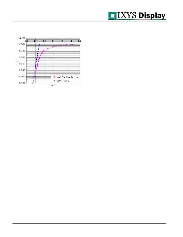
�For� comparison,� the� second� curve� is� the� “ideal”� curve�
�obtained� if� ?� =1� and� R� S� =� 0� (with� the� same� V� F� turn� on�
�voltage).�
�Figure� A3.1:� I-V� characteristic� for� Nichia� WLED� diode�
�(NSSW020BT-P1�
�The� LDS8160� implements� LED� temperature�
�measurement� using� two� low� currents� during� PWM� off�
�time.� Low� currents� are� used� to� avoid� error� due� high�
�LED’� R� S� value� and� LED� heating� during� measurement.�
�The� sampling� time� is� ~� 125usec� per� LED� sensed�
�every� 2.5� sec.� The� interruption� and� change� in� the�
�average� LED� current� is� ~� 0.015%� in� the� sampling�
�period� and� ~0.6%� error� in� the� local� 20msec� time�
�window� of� the� measured� sample.� This� is� below� the�
�level� to� have� any� visual� effect.�
�LDS8160� allows� LED� sensing� on� three� LED� driver�
�channels� (1� per� each� bank� or� color� channel).� The�
�temperature� may� be� measured� on� any� LED� (R,� G,� B,�
�WLED,� or� other)� connected� to� the� LEDA1,� LEDB1,� or�
�LEDC1� driver� channels.� This� allows� users� to�
�determine� the� junction� temperature� for� one� LED� for�
�each� of� the� three� Banks� (or� color� channels).�
�Additional� correction,� based� on� measurements� of� an�
�on-chip� silicon� diode’s� temperature� data,� improves�
�measurement� precision.�
�The� LDS8160� performs� a� calibration� routine� at� start-�
�up� to� determine� the� ideality� factor� ?� for� the� LEDs�
�used.� In� addition,� this� calibration� process� may� be�
�conducted� at� user� (system)� defined� operating� points.�
�During� the� calibration� sequence,� the� junction�
�temperature� Tj� of� the� on-chip� silicon� diode� is�
�measured� and� the� ambient� temperature� Ta� is�
�obtained� by� applying� a� stored� offset� between� Tj� and�
�Ta.� This� offset� depends� on� LDS8160� package�
�thermal� resistance,� the� user� selected� operating�
�condition,� and� the� device� power� levels� during� the�
�calibration� sequence.� Factory� defaults� are� provided�
�but� can� be� reprogrammed� by� the� user.�
�A� thermal� related� package� offset� for� the� LEDs� must�
�also� be� stored� (based� on� LED� vendor� thermal� data)�
�to� further� correlate� LED� Tj� with� the� silicon� diode� Tj�
�and� the� Ta� during� the� calibration� process.�
�This� additional� LED� based� package� offset� should� be�
�loaded� by� the� user,� based� on� user’s� selection� of�
�LEDs� and� operating� conditions� during� the� desired�
�calibration� sequence.�
�The� user� decides� the� operating� condition� for� running�
�the� calibration� sequence,� and� initiates� a� calibration�
�command� by� writing� bit� 4� of� Register� 1Fh� to� “1”� (the�
�bit� resets� automatically� upon� completion).�
�If� the� calibration� starts� prior� to� setting� currents� to� the�
�LEDs,� (i.e.� after� the� power-on� initialization� sequence�
�for� the� LDS8160),� then� during� the� calibration� period,�
�we� assume� that� the� ambient� temperature,� Ta,� is� the�
�same� for� both� the� on-chip� diode� and� the� LEDs� (since�
�no� DC� current� flow� in� LEDs,� there� is� no� appreciable�
�temperature� offset� incurred).�
�The� LEDs� also� have� a� typical� offset� between� junction�
�and� ambient� temperature,� which� is� applied� to� obtain�
�the� reference� LED� Tj� used� for� calibrating� the� ideality�
�factor� as� prior� discussed.�
�The� LDS8160� is� delivered� with� factory-preset� values,�
�however,� the� user� must� load� LED� specific� parameters�
�and� recommended� factory� values� for� the� internal�
�silicon� diode.�
�Ta-Tj� Temperature� Offset� adjustment� for� silicon� diode�
�0�
�offset,� with� +35oC� to� -40oC� range);�
�Ta-Tj� Temperature� Offset� for� LEDs� –� register� 49h,�
�0�
�to� -40oC� range););�
�Silicon� diode� V� F� temperature� coefficient� –� register�
�A0h,� bit� 7� –� bit0;� factory� recommended� load� value� dis�
�-1.71� mV/°C� =� 00110110� (bin)� =� 36h�
�Silicon� diode� ideality� coefficient� –� register� C0h;�
�factory� recommended� load� values� is� 1.000� =�
�01000000(bin)� =� 40h�
�Temperature� Offset� between� Tj� and� Ta� for� LED� –�
�register� D0h� (user� loaded)� -� correction� from� ambient�
�temperature� to� LED� junction� temperature;� factory�
�default� =� 04h.�
�Temperature� Offset� between� Tj� and� Ta� for� silicon�
�diode� –� register� D2h,� correction� for� LDS8160�
�package� thermal� characteristics;� factory� default� =02h.�
�LEDs� Rs� value� (user� loaded)� for� Banks� A,� B,� and� C�
�registers� D6h,� D8h,� and� DAh� respectively.�
�?� 2009� IXYS� Corp.�
�Characteristics� subject� to� change� without� notice�
�32�
�Doc.� No.� 8160_DS,� Rev.� N1.0�
�发布紧急采购,3分钟左右您将得到回复。
相关PDF资料
LDS8620-002-T2
IC LED DRIVER FLASH 16WQFN
LDS8621002-T2-960
IC LED DRIVER FLASH 16WQFN
LDS8680008-T2
IC LED DRIVER PHOTO FLASH 16WQFN
LDS8681008-T2
IC LED DRIVER PHOTO FLASH 16WQFN
LDS8711
IC LED DRIVER PWM 32MA 8TDFN
LDS8720
IC LED DRIVER PWM 25MA 8TDFN
LDS8724
IC LED DRIVER PWM 25MA 8TDFN
LDS8726
IC LED DRIVER PWM 25MA 8TDFN
相关代理商/技术参数
LDS8161-002-T2
功能描述:LED照明驱动器 6-Chan High-Side WLED Driver
RoHS:否 制造商:STMicroelectronics 输入电压:11.5 V to 23 V 工作频率: 最大电源电流:1.7 mA 输出电流: 最大工作温度: 安装风格:SMD/SMT 封装 / 箱体:SO-16N
LDS85-750
制造商:未知厂家 制造商全称:未知厂家 功能描述:Analog IC
LDS8620-002-T2
功能描述:LED照明驱动器 200mA Dual Output Flash/Lamp Drvr
RoHS:否 制造商:STMicroelectronics 输入电压:11.5 V to 23 V 工作频率: 最大电源电流:1.7 mA 输出电流: 最大工作温度: 安装风格:SMD/SMT 封装 / 箱体:SO-16N
LDS8621-002-T2
功能描述:LED照明驱动器 200mA Dual Output Flash/Lamp Drvr
RoHS:否 制造商:STMicroelectronics 输入电压:11.5 V to 23 V 工作频率: 最大电源电流:1.7 mA 输出电流: 最大工作温度: 安装风格:SMD/SMT 封装 / 箱体:SO-16N
LDS8621002-T2-960
功能描述:IC LED DRIVER FLASH 16WQFN RoHS:是 类别:集成电路 (IC) >> PMIC - LED 驱动器 系列:PowerLite™ 标准包装:60 系列:- 恒定电流:- 恒定电压:- 拓扑:线性(LDO),PWM,升压(升压) 输出数:8 内部驱动器:是 类型 - 主要:背光 类型 - 次要:RGB,白色 LED 频率:500kHz ~ 1.5MHz 电源电压:4.75 V ~ 26 V 输出电压:45V 安装类型:* 封装/外壳:* 供应商设备封装:* 包装:* 工作温度:-40°C ~ 85°C
LDS8640-002-T3
功能描述:LED照明驱动器 400mA Dual Output Flash/Lamp Drvr
RoHS:否 制造商:STMicroelectronics 输入电压:11.5 V to 23 V 工作频率: 最大电源电流:1.7 mA 输出电流: 最大工作温度: 安装风格:SMD/SMT 封装 / 箱体:SO-16N
LDS8640-008-T2
功能描述:IC LED DRIVER 200MA 16WQFN RoHS:是 类别:集成电路 (IC) >> PMIC - LED 驱动器 系列:PowerLite™ 标准包装:60 系列:- 恒定电流:- 恒定电压:- 拓扑:线性(LDO),PWM,升压(升压) 输出数:8 内部驱动器:是 类型 - 主要:背光 类型 - 次要:RGB,白色 LED 频率:500kHz ~ 1.5MHz 电源电压:4.75 V ~ 26 V 输出电压:45V 安装类型:* 封装/外壳:* 供应商设备封装:* 包装:* 工作温度:-40°C ~ 85°C
LDS8641-002-T4
功能描述:LED照明驱动器 400mA Dual Output Flash/Lamp Drvr
RoHS:否 制造商:STMicroelectronics 输入电压:11.5 V to 23 V 工作频率: 最大电源电流:1.7 mA 输出电流: 最大工作温度: 安装风格:SMD/SMT 封装 / 箱体:SO-16N